Bode Plot Maker: Your Ultimate Guide to Easy Bode Plots
Frequency response analysis, a cornerstone of control systems engineering, relies heavily on visual representations like Bode plots. MATLAB, a powerful computational tool, provides functions for generating these plots, but understanding their underlying principles is crucial. A skilled engineer can utilize a bode plot maker effectively for system design and analysis. For those new to the field, the IEEE offers resources to enhance their comprehension of Bode plot creation and interpretation.
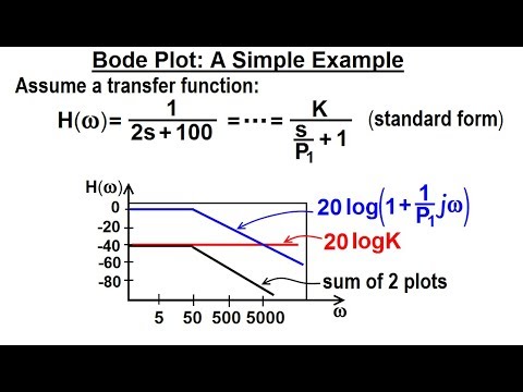
Image taken from the YouTube channel Michel van Biezen , from the video titled Electrical Engineering: Ch 15: Frequency Response (18 of 56) Bode Plot: A Simple Example .
Crafting the Perfect Article: "Bode Plot Maker: Your Ultimate Guide to Easy Bode Plots"
This guide outlines the optimal structure for an article about Bode plot makers, ensuring clarity, comprehensiveness, and ease of understanding for the reader. We’ll focus on leveraging the keyword "bode plot maker" effectively throughout the content.
1. Introduction: What is a Bode Plot and Why Use a Bode Plot Maker?
- Hook: Begin with a compelling reason why the reader should care about Bode plots. Perhaps highlight a common problem in circuit analysis that Bode plots solve.
- Explain Bode Plots Simply: Define Bode plots in a non-technical way, focusing on what information they convey (frequency response of a system). Example: "A Bode plot is a visual representation of how a circuit or system responds to different frequencies. It shows you how much the signal is amplified (gain) and how much it’s delayed (phase shift) at each frequency."
- Introduce the "Bode Plot Maker" Concept: Explain what a Bode plot maker is and its function. Frame it as a tool to simplify the process of creating Bode plots. Example: "Creating Bode plots manually can be time-consuming. A Bode plot maker is software or a tool that automates this process, allowing you to quickly visualize your system’s frequency response."
- Highlight Key Benefits of Using a Bode Plot Maker: List practical advantages, such as speed, accuracy, ease of use, and the ability to handle complex systems. Use bullet points for clarity:
- Saves time and effort.
- Reduces the chance of manual calculation errors.
- Allows for easy manipulation and experimentation.
- Supports various file formats for import and export.
- Briefly Mention Different Types of Bode Plot Makers: Tease the different options (software, online tools, etc.) which will be detailed later in the article.
2. Understanding the Fundamentals: Building Blocks for Effective Use
- Gain and Phase: Explain gain and phase shift – the two components of a Bode plot. Use simple language and avoid overly technical formulas initially.
- Gain (Magnitude): Describe gain as the amplification or attenuation of a signal at a specific frequency. Relate it to decibels (dB) in a clear, understandable way.
- Phase Shift: Explain phase shift as the time delay introduced by the system at a specific frequency. Relate it to degrees or radians.
- Axes of a Bode Plot: Describe the axes – frequency (logarithmic scale) on the x-axis and gain (dB) and phase (degrees) on the y-axis. A simple diagram or illustration would be highly beneficial here.
- Key Bode Plot Characteristics:
- Cutoff Frequency: Define the cutoff frequency and its significance in determining the bandwidth of the system.
- Roll-off Rate: Explain the roll-off rate (dB/decade) and how it relates to the order of the system.
- Resonance Peaks: Discuss resonance peaks and their implications for system stability.
-
Table Example: Summarize these elements in a table:
Characteristic Description Significance Cutoff Frequency Frequency where gain drops by 3 dB. Defines the bandwidth of the system. Roll-off Rate Rate at which gain decreases with frequency. Indicates the order of the system and its stability. Resonance Peak Peak in the gain plot. Indicates potential instability or oscillations.
3. Exploring Different Types of Bode Plot Makers
- Software-Based Bode Plot Makers:
- Description: Detail software options, both free and paid, like MATLAB, Python libraries (e.g., SciPy, Control Systems Toolbox), or dedicated circuit simulation software.
- Pros: High customization, powerful features, suitable for complex analysis.
- Cons: May require programming knowledge, can be expensive, steeper learning curve.
- Online Bode Plot Makers:
- Description: Present web-based tools that allow users to create Bode plots directly in their browser. Include examples of popular online tools.
- Pros: Convenient, no installation required, often free or low-cost, user-friendly interface.
- Cons: Limited functionality compared to software, may require an internet connection.
- Handheld Bode Plot Makers (less common):
- Description: Discuss any handheld or portable devices that can generate Bode plots. These are less common but might be relevant for specific use cases.
- Pros: Portability, dedicated hardware.
- Cons: Limited functionality, potentially expensive, may require specialized knowledge.
4. A Step-by-Step Guide to Using a Bode Plot Maker
-
Using a Software-Based Bode Plot Maker (Example: Python with SciPy):
- Installation: Briefly explain how to install Python and necessary libraries (SciPy, Matplotlib).
-
Code Example: Provide a simple code snippet that defines a transfer function and generates a Bode plot. Annotate the code clearly. Example:
import scipy.signal as signal

import matplotlib.pyplot as plt
# Define the transfer function (example)
num = [1]
den = [1, 1, 1] # s^2 + s + 1
system = signal.TransferFunction(num, den)# Generate the Bode plot
w, mag, phase = signal.bode(system)# Plot the results
plt.figure()
plt.subplot(2, 1, 1)
plt.semilogx(w, mag)
plt.ylabel('Magnitude (dB)')
plt.grid(True)plt.subplot(2, 1, 2)
plt.semilogx(w, phase)
plt.ylabel('Phase (degrees)')
plt.xlabel('Frequency (rad/s)')
plt.grid(True)plt.show()
- Explanation: Explain each line of code, focusing on how it relates to creating the Bode plot.
- Using an Online Bode Plot Maker (Example: Online Tool):
- Tool Selection: Choose a popular and user-friendly online Bode plot maker.
- Inputting the Transfer Function: Guide the user on how to enter the transfer function, highlighting different input formats the tool supports.
- Generating the Plot: Show how to generate the Bode plot with the tool and any available customization options (e.g., frequency range, axis scaling).
- Interpreting the Plot: Briefly explain how to read and interpret the generated Bode plot.
5. Advanced Techniques and Applications
- Analyzing Complex Systems: Discuss how to use Bode plots to analyze more complicated systems, such as cascaded circuits or feedback control systems.
- Stability Analysis: Explain how to use Bode plots to determine the stability of a system, focusing on gain margin and phase margin.
- Filter Design: Show how Bode plots can be used to design filters with specific frequency responses. Provide examples of different filter types (low-pass, high-pass, band-pass).
- Troubleshooting Circuit Problems: Explain how Bode plots can help diagnose problems in circuits, such as oscillations or unwanted frequency responses.
- Simulation and Verification: Explain how to use a "bode plot maker" as a verification tool to validate designs simulated using software.
6. Common Mistakes to Avoid When Using a Bode Plot Maker
- Incorrect Transfer Function Input: Stress the importance of accurately entering the transfer function. Show examples of common errors.
- Misinterpreting the Axes: Emphasize understanding the logarithmic frequency scale and the units for gain and phase.
- Ignoring Important Frequency Ranges: Advise users to select an appropriate frequency range to capture the relevant behavior of the system.
- Over-Reliance on the Tool: Warn against blindly trusting the output of the Bode plot maker without understanding the underlying principles.
- Not validating assumptions about linear systems. Explain the limitations of Bode Plots in cases of non-linear systems.
This structure provides a comprehensive guide to using a "bode plot maker," ensuring the article is informative, instructional, and easily understandable for readers of varying technical backgrounds. By focusing on practical examples and clear explanations, the article will empower readers to effectively use Bode plot makers for their own projects and analyses.
Bode Plot Maker FAQs: Quick Answers to Your Questions
Got questions about creating Bode plots? This FAQ section provides concise answers to common queries about using a bode plot maker to simplify the process.
What is a Bode plot and why is it useful?
A Bode plot is a graph showing the magnitude and phase response of a system as a function of frequency. It’s useful for analyzing the stability and performance of control systems and electronic circuits. Using a Bode plot maker can significantly speed up this analysis.
What kind of transfer functions can a Bode plot maker handle?
Most Bode plot makers can handle a variety of transfer functions, including those with poles, zeros, and gain factors. Complex transfer functions can also be handled. The specific capabilities depend on the particular bode plot maker.
Can a Bode plot maker help me design better control systems?
Yes, by visualizing the frequency response, a Bode plot maker allows you to quickly identify potential stability issues and tune your control system parameters accordingly. This leads to improved performance and robustness.
What are the advantages of using a Bode plot maker over manual calculation?
Using a bode plot maker saves time and reduces the risk of calculation errors compared to manual plotting. It provides a visually clear and accurate representation of the frequency response, making it easier to analyze and optimize your designs.
And there you have it! Hopefully, our guide has made using a bode plot maker a little less daunting. Now go forth and conquer those frequency responses!